
STPA Primer
STPA looks for the ways a system could cause harm, even when every part works, so they can be fixed before anyone is hurt.
Page Overview
STPA’s Focus
- 1Four Conditions for Control
What any controller needs in order to control a process safely.
- 2Anticipating How Controllers Get Confused
The well-known ways control loops break down, seen in a hospital and in a winter takeoff.
How STPA Works
- 3The Four Steps of STPA
What each step involves, and the constraints and solutions it produces.
- 4Steps 1–4: A Worked Example
A shift-by-wire car design, analyzed step by step.
- 5More Scenarios, Same Questions
Other ways the same unsafe control action can happen, and the short set of questions that finds them.
- 6Blind Tests: Can You Prove STPA Works?
How STPA compared with HAZOP, FTA, and FMEA on a real design flaw.
Part 1 of 6
Four Conditions for Control
Builds on: The Control Loop Model, on About STAMP
Effective control, whether by a person, a piece of software, or an organization, requires four conditions. Accidents almost always involve one of these conditions being broken somewhere in the system.
Goal Condition
The controller has the right goals, and gives them the right priority.
In the diagram: Decision Making
Model Condition
The controller has a model of the process’s current state, and of how that state can change.
In the diagram: Process Model
Action Condition
The controller has the authority and the means to act on the process.
In the diagram: Control Actions
Observability Condition
The controller can find out the current state of the process.
In the diagram: Feedback
Next come two examples of how these conditions break down. They show which patterns to look for and how the interactions in a control loop reveal flaws in a complicated system before anything goes wrong.
Part 2 of 6
Anticipating How Controllers Get Confused
Control loops break down in a few well-known ways, often without anything failing. A controller’s beliefs about the process drift away from what’s really happening. People and automation each assume the other is in charge. The feedback a controller needs was never designed in, or it comes too late, or it misleads. The same patterns show up whether the controller is a person or software.
Because the patterns are known, STPA goes looking for them. The patterns are intuitive, so they’re easy to spot in a design and can be fixed before they lead to a costly accident.
STPA compared with FMEA, Fault Tree Analysis, and HAZOP
Example: Reviewing Lab Results
The Nurse Practitioner’s Control Loop
Step through what STPA finds:
1The Control Loop
Before surgery, a nurse practitioner checks that the patient is ready. The nurse practitioner orders blood tests and reads the results in the patient’s electronic health record, where results outside the normal range are flagged in red. If a result is worrying, the nurse practitioner can refer the patient to a specialist before surgery goes ahead.
2Questions from STPA
- When could the nurse practitioner skip a referral the patient needs?
- Could a result be abnormal and the feedback still show no red flag?
- What would the nurse practitioner believe about a result with no flag?
3The Loss Scenario
The answers add up to a loss scenario. An abnormal result shows in plain black, with no red flag, so the nurse practitioner believes all the results are normal and doesn’t refer the patient.
The Loss Scenario, Step by Step
- Control action
- The nurse practitioner doesn’t refer the patient to a specialist.
- Process model (beliefs)
- The nurse practitioner believes all the patient’s results are normal.
- Feedback
- The result is never flagged in red, even though it’s abnormal. Why? The lab system wasn’t designed for tests like this one, whose normal range depends on the time of day the blood is drawn. The system holds one fixed range per test, so this test’s range was left blank, and its results always show in plain black, just like a normal result. Nothing has failed: the record shows exactly what it was set up to show.
- Patient
- The low hormone level goes untreated, which can be dangerous during surgery.
Fixes for the Control Loop
- Feedback: Ensure the system can flag tests whose normal range changes through the day, and that any result it still can’t flag says “not flagged” on screen instead of showing in plain black like a normal one.
- Process model (beliefs): Ensure clinicians know which tests aren’t flagged, so plain black isn’t read as normal.
This scenario is based on a real case. Read the 2024 MIT report
More Technical Example: A Winter Takeoff
An airliner is about to take off on a winter day. To set takeoff thrust, the crew pushes the thrust levers forward until a thrust gauge in the cockpit shows a target number. The gauge gets its reading from a small sensor in each engine’s air intake. Heaters, called anti-ice, keep ice off the intakes and those sensors. What could go wrong?
Human Error View
Model: crew tasks
What could go wrong
- The crew could forget to switch on engine anti-ice.
- The crew could call out “thrust set” when it isn’t.
Fix
Train crews on winter operations and thrust checks, and make sure the checklist covers anti-ice.
Assumes a trained crew with a checklist will use anti-ice when it’s needed.
Function Failure View
Model: functions
What could go wrong
- Partial loss of thrust during takeoff.
- Loss of engine anti-ice.
Effect
The engine thrust warning alerts the crew, who stop the takeoff or return to land. If the engine thrust warning also fails, the airplane may not climb safely.
Assumes the design warns the crew, and looks for failures that could stop the warning.
STPA View
Model: a control loop
What could go wrong
- Control action: the crew could stop pushing the thrust levers too soon, or leave anti-ice off.
- Process model (beliefs): the crew could believe takeoff thrust is set when it’s too low, or that the autothrottle is still adjusting thrust after it has stopped.
- Feedback: the thrust gauge could show full takeoff thrust while the engines give too little.
Doesn’t assume anything failed.
Answering the STPA Questions
The Crew’s Control Loop
STPA is scenario-based. Starting from what could go wrong, the team answers questions about the crew’s control loop. The answers build a loss scenario: a step-by-step account of how a loss could happen.
Questions from STPA
- Why might a trained crew leave anti-ice off?
- How could ice be forming while the crew believes anti-ice isn’t needed?
- Could the engines do what they’re told and still produce too little thrust?
- What would the crew see if the engines gave less thrust?
The Loss Scenario
Anti-Ice
- Control action
- The crew leaves anti-ice off.
- Process model (beliefs)
- The crew believes anti-ice isn’t needed.
- Feedback
- It’s warm out, and any snow the crew can see is melting. Nothing looks icy.
- Engines
- Ice builds up on the intake sensors, where the crew can’t see it, because air cools as it speeds into the engines.
Takeoff Thrust
- Control action
- The crew stops pushing the thrust levers forward while thrust is still too low.
- Process model (beliefs)
- The crew believes thrust is high enough for takeoff.
- Feedback
- The iced sensors make the thrust gauge read high, so it shows takeoff thrust. No warning comes on for the ice or the low thrust: the airplane has no way to detect either. The engine speed gauges read a little low, which is easy to miss while watching the runway, and on a snowy runway the slow speed-up looks normal.
- Engines
- The engines do what the levers tell them, so they give less thrust than the takeoff needs.
Both beliefs are clearly wrong in hindsight. Understanding how these beliefs form, from what the crew can see at the time, is what makes it possible to prevent them.
Fixes for the Crew’s Control Loop
- Control action: Ensure sensor heat comes on by itself in cold, wet weather, so the crew doesn’t have to decide when it’s needed.
- Process model (beliefs): Ensure the checklist says engine ice can form above freezing, even when nothing looks icy.
- Feedback: Ensure the crew is alerted when the thrust gauge and the engine speed gauges disagree, or when the airplane is too slow for how far it has gone down the runway.
Part 3 of 6
The Four Steps of STPA
The four steps produce constraints and solutions. The first ones cover the whole system, and later ones get more specific.
-
1
What you do
Define the Purpose of the Analysis
Identify the losses that stakeholders can’t accept and the system-level hazards that could lead to them.
What you get
System-Level Constraints
High-level constraints the whole system has to meet to prevent the hazards. They drive the more detailed constraints and solutions in the steps that follow.
-
2
What you do
Model the Control Structure
Map the controllers (people, software, automation, and organizations), the control actions they can take, and the feedback they get.
What you get
Constraints on the Control Structure
What the system has to provide for control to work: the control loops that must exist, the control actions each controller can use, the responsibilities each one has, and the feedback each one relies on.
-
3
What you do
Identify Unsafe Control Actions
Find the contexts in which a control action would be unsafe: when it isn’t provided, when it is provided, when it comes too early, too late, or out of order, and when it’s stopped too soon or applied too long.
What you get
Controller Constraints
An unsafe control action becomes a constraint on the controller: what it must or must not do in that context.
-
4
What you do
Identify Loss Scenarios
Work out why an unsafe control action could happen, or why a safe one might not get carried out: what the controller believed, what feedback it had, and what the process itself did.
What you get
Requirements and Other Solutions
Solutions aimed at specific scenarios: requirements, design changes, test cases, procedures, training, and leading indicators to watch in operation.
Part 4 of 6
Steps 1–4: A Worked Example
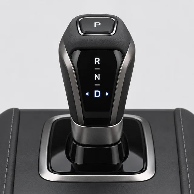
Carmakers are replacing mechanical controls with electronic ones. Braking, steering, acceleration, and gear shifting are moving to “by-wire” designs, where a control sends an electrical signal instead of moving a cable or linkage, with no mechanical backup. This example uses STPA to look for weaknesses in a shift-by-wire design, and to work out solutions.
In the design analyzed here, the shift lever springs back to the center after every shift, like a joystick. From D, pushing the lever forward one click selects N, and two clicks in one push select R. Pushing forward from R does nothing more. Park has its own P button on top of the knob. Unlike a traditional P-R-N-D lever, this lever gives the driver no way to tell the gear by looking at it or feeling where it is. Drivers can tell the gear only from a letter on the shift knob and on the dashboard.
The design has safeguards to help protect against unintended use or misuse. The engine won’t switch off unless the vehicle is in Park, and a chime sounds if the driver’s door opens when the vehicle isn’t in Park.
Step 1: Losses, Hazards, and Constraints
Step 1 starts with the losses to prevent. The system-level hazards are states of the whole vehicle that could lead to those losses, and the system-level constraints say what the vehicle must do to prevent each hazard.
Losses
- L-1People hurt or killed: the driver, passengers, or people nearby
- L-2Damage to the vehicle or other property
Hazards
- H-1An unattended vehicle is moving [L-1, L-2]
- H-2A moving vehicle is locked in Park [L-1, L-2]
What you get
System-Level Constraints
- SC-1An unattended vehicle must stay still [H-1]
- SC-2A moving vehicle must not be locked in Park [H-2]
Step 2: The Control Structure
The driver picks a gear with the shift lever, selects Park with the P button, and turns the engine on and off with a Start/Stop button. Software reads the lever and the buttons, and sends the commands to the transmission and the engine.
To tell what the car is doing, the driver has a letter showing the gear on the shift knob and on the dashboard, a chime if the door opens when the car isn’t in Park, and the sound of the engine.
Put together, these controls and this feedback can be sketched as a control structure, with control actions going down and feedback coming up.
Control Structure (Simplified)
What you get
Constraints on the Control Structure (Examples)
- CS-1The driver must be able to tell which gear the vehicle is in by feel or at a glance. [SC-1]
- CS-2The driver must be able to tell whether the engine is still running. [SC-1]
- CS-3The software shares the job of keeping a parked vehicle still, for when the driver leaves without shifting to Park. [SC-1]
- CS-4The software must be able to tell whether the driver is still in the vehicle. [SC-1, SC-2]
Step 3: Unsafe Control Actions
Shifting into Park keeps a parked car still, so we’ll analyze that control action. A control action can be unsafe in four ways, depending on the context.
| Control Action | Not Providing Causes Hazard | Providing Causes Hazard | Too Early, Too Late, or Out of Order | Stopped Too Soon or Applied Too Long |
|---|---|---|---|---|
| Driver shifts to Park | UCA-1Driver doesn’t shift to Park when getting out with the engine running [H-1] | Not hazardous on its own: the software won’t engage Park while the vehicle is moving | UCA-2Driver shifts to Park too early, before the vehicle has stopped [H-1] | Not applicable: shifting is a single action |
| Software engages Park | UCA-3Software doesn’t engage Park when the driver has left and the vehicle isn’t in Park [H-1] | UCA-4Software engages Park while the vehicle is being driven [H-2] | UCA-5Software engages Park too late, after the vehicle has started to roll [H-1] | Not applicable: engaging Park is a single action |
What you get
Controller Constraints (Examples)
- C-1The driver must shift to Park when getting out with the engine running. [UCA-1]
- C-3The software must engage Park when the driver has left and the vehicle isn’t in Park. [UCA-3]
- C-4The software must not engage Park while the vehicle is being driven. [UCA-4]
Together, C-3 and C-4 mean any fix has to tell whether the driver has left or is still driving.
Step 4: A Loss Scenario
Step 4 takes UCA-1 and works back through the driver’s control loop: what they did, what they believed, why the decision made sense, and what feedback led them there.
Scenario for UCA-1
- Unsafe control actionDriver doesn’t shift to Park when getting out with the engine running
- Process modelBelieves the vehicle is in Park
- Decision making“If it’s in Park, I can step out.”
- FeedbackFelt two clicks forward, like a lever moving into Park; only a small letter shows the gear
Actually: in Reverse
The scenario: to park, the driver pushes the lever forward from D and feels it click forward twice, the way a traditional lever feels moving up into Park. The lever has actually selected R. Believing the vehicle is in Park, the driver gets out with the engine running, and the vehicle starts to roll backward.
What you get
Requirements and Other Solutions (Examples)
The vehicle must shift itself into Park if the driver leaves while it isn’t in Park.
A shift lever that stays where it’s put, so the driver can feel which gear it’s in.
Get out with the engine running in each gear, and check that the vehicle stays still.
Check for the P and set the parking brake before getting out.
This Design Was Real
In 2016, about 811,000 cars and SUVs in the US with a shifter like this were recalled, after drivers got out believing the vehicle was in Park and it rolled away. NHTSA counted 266 crashes and 68 injuries, and no part had failed. The changes made afterward match the solutions above: “Auto Park” software, a shifter that stays in the selected gear on later models, and a reference card for owners.
STPA had already flagged this problem. At the 2016 STAMP Workshop, a month before the recall, GM engineers presented an STPA of shift-by-wire controls whose top-priority unsafe control action was a driver not putting the car in Park before getting out.
Part 5 of 6
More Scenarios, Same Questions
Step 4 usually finds more than one scenario for an unsafe control action. The scenarios come from asking about the parts of the control loop: the feedback, the controller’s beliefs and decisions, other controllers, and the process itself. Here are more for UCA-1.
What could hide the gear from the driver?
Two clicks forward from D select R, which feels like moving a traditional lever into Park, and only a small letter shows the gear.
This is the scenario in Part 4.
Does the warning come in time?
The chime and the dashboard message start when the door opens, as the driver is already getting out.
Could something else in the car override what the driver did?
The driver presses Start/Stop to switch off. A safety interlock keeps the engine running because the vehicle isn’t in Park, and the idle is quiet, so the driver gets out believing the car is off and parked.
Reported to NHTSA
Could the car do something different from what the driver chose?
The driver selects Park while the vehicle is still rolling a little. Above 1.2 mph the transmission goes to Neutral instead, and says so only on the dashboard.
Reported to NHTSA
When would leaving the engine running make sense?
The driver means to leave the engine running, and steps out believing the vehicle is in Park.
Reported to NHTSA
What could go wrong with the fix?
Auto Park decides the driver has left by checking the door, the seat belt, and the brake pedal. The same questions apply to Auto Park: when could those signals be wrong?
Three of these are scenarios that NHTSA later documented from drivers’ reports. Those reports come in after vehicles are on the road, when fixes cost the most. Teams don’t have to wait for those reports. STPA can find the same scenarios early in design. The STPA questions that found these scenarios are the same for any unsafe control action, and each scenario takes a sentence or two to write.
STPA Found This Two Years Before the Recall
STPA work on shift-by-wire controls had already anticipated this problem, before it led to crashes, injuries, and a recall likely costing tens of millions of dollars. The work was done at a different carmaker, GM, with MIT researchers including Dr. John Thomas.
The Same Pattern Elsewhere
Other cars have misled drivers in the same way, with nothing broken:
- With keyless ignition, drivers have walked away from cars they thought were switched off but were still running, or weren’t in Park. NHTSA proposed a rule on both risks.
- An SUV was recalled in 2015 because its engine Start/Stop button sat among the push-button gear selectors, and people switched the engine off by mistake while driving.
Which Fixes Work Best
Many fixes don’t need ranking. If a scenario shows a missing requirement, such as a car that doesn’t shift itself into Park when the driver has left, and the fix is easy, add it.
Ranking by probability was designed for random component failures, where a part may work for thousands of hours before it fails, so you need a way to judge how long it will last. A flaw in a design, a requirement, or a procedure is different: it’s in every product built to that design from the first day, and it causes trouble in a predictable, non-random way.
When there’s a real choice between fixes, system safety standards rank them by how well they work. This is the order in MIL-STD-882E, the U.S. Department of Defense’s standard practice for system safety.
- aEliminate the hazard
- bReduce the risk by changing the designThe new shifter
- cAdd engineered features or devicesAuto Park
- dProvide warning devicesThe door chime
- eSigns, procedures, training, and protective equipmentThe owner card
Most effective: fix the system that people operate in.
Least effective: fix the people who operate in the system.
Part 6 of 6
Blind Tests: Can You Prove STPA Works?
It’s easy to assume a safety analysis method works because it’s familiar, required, or widely used. The only way to know for sure is to test the method: does it find real flaws that matter in real systems?
A fair test needs a system with flaws that are already known, and analysis teams who don’t know what they are. Each team uses a different method, ideally with years of professional experience in it, and then the results are compared.
EPRI (the Electric Power Research Institute) decided to test which methods could uncover real flaws when the analysis teams don’t know the answers. EPRI picked the emergency cooling system of a nuclear power plant, where a design flaw had already shut it down during a start, at a cost of more than $10 million, and no component had failed.
The analysis teams weren’t told about the flaw. The teams using HAZOP, FTA, FMEA, and other methods had years of experience with them. The STPA team had just finished a one-day STPA class with Dr. John Thomas.
What the Teams Found
Every method found most of the component failures.
Only STPA found the flaws in the digital control design and its assumptions, including the scenario that had happened.
Based on these results, STPA was chosen for EPRI’s new guidance on engineering digital instrumentation and control in nuclear plants.
Methods built on different views of a system each bring their own perspective, so we can expect a method with a different model to uncover things the others missed. STPA’s strengths are software, autonomy, and human behavior, where complex interactions are easy to overlook, even by experts and in design reviews. STPA can start in the concept phase, and teams often use STPA throughout development and operations.
STPA has limits too. STPA doesn’t model physical proximity, such as parts close enough to damage each other, and because STPA looks at more than failures, a probability doesn’t apply to every STPA result. FMEA and FTA are the other way around: they model failures of known functions and components, and assign probabilities to those failures.
Results in Other Industries
Teams in aviation, space, defense, automotive, maritime, and healthcare have compared STPA with the methods they already used. A few of the results:
- Missile defense: the system had been analyzed with failure-based methods, and STPA was tried only near the end, with no one expecting it to find much. In three months, STPA found so many flaws that engineers spent six months going back to revisit and fix earlier design decisions. Looking back, the common reaction among the engineers was that they should have tried STPA much earlier.
- Aircraft engine controls: STPA found 30 scenarios that the standard methods missed, and later in service, flaws turned up that exactly matched what STPA had found years before.
- Spacecraft (JAXA): STPA found the failures in the existing fault tree analysis, plus catastrophic causes the fault tree had missed.
- FMECA comparison: of 137 causes STPA found, 53 weren’t covered by the FMECA.